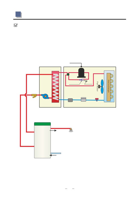
2.3 Küttelahendused
3: Põrandaküte ja eelsoendatud tarbevesi.
Tarbeveele on vajalik eraldi spiraal.
Eelsoendatud-
Tarbevesi
Pump1
Põrandaküte
Tarbevee sisend
Tühjendus
Põrandaküte ja eelsoendatud tarbevesi.
4: Maja küte ja soe tarbevesi.
Päikesekollektor
Soe tarbevesi (. .)
Pump 3
Toa Temp.1
El küttekeha.
E1
Radiaator
Pump 2
Põrandaküte
Toa Temp.2
Tarbevesi sisse
Tühjendus
Soojuspump Päikesekollektor
Küte ja soe tarbevesi
25
2.4 Installation
■ Indoor unit installation
For the installation of the indoor unit, please refers to the followings:
Locating
cardboard
1.Use the locating cardboard to
2.Drill the holes on the wall.
mark the positions of the indoor unit
on the wall.
Expansion bolt
3.Insert the expansion bolts (Terminal
4.Hang the indoor unit on the
diameter less than 16mm) into the
expansion bolts.
holes.
Note: The wall must strong enough to hang the unit on.
weather
enclosure
The refrigerant piping and signal cable
penetration
between indoor,outdoor unit should go
sleeve
through the wall by using a wall sleeve.
26
2.4 Installation
■ Outdoor unit installation
1. The unit must be located on a flat, solid, preferably cemented
surface.
2. when installing the unit, introduce a tilt of 1 cm/ m for rain water
evacuation
3. when installing the unit in harsh climatic conditions, sub-zero
temperatures, snow, humidity.., it is recommended to raise the unit off the
ground by about 20cm.
4.It is recommended to have a base with following size for these units:
5.Rubber vibration absorbing mountings are recommended.
6.When sitting the unit, take care to leave sufficient free space all around
it for carrying out maintenance.
2
3
1
NO
AVH-12V1D
AVH-24V1D
1
1028
1094
2
738
906
3
300
300
1. Fix the bracket on the wall with expansion bolts.
2. Place the outdoor unit on the bracket. A vibration absorber is
recommended to
reduce the noise of the outdoor unit.
3. Fix the unit to the bracket.
27
2.4 Installation
■ Wiring
Precaution:
1.It is recommended to use a suitable breaker for the heat pump and make
sure the power supply to the heater corresponds to the
specifications. Otherwise the unit might be damaged.
2.The power supply to the heat pump unit must be grounded.
3.Cable should be fixed tightly, to ensure it won't get lossen.
1.Take off the screw on the side of
2.Open the indoor unit.
the unit.
3. Take off the cable fixture and
4. Connect the power cable to the
insert the power cable through the
terminal block.
fixture(customer can choose
Please refers to the wiring diagram
which cable fixture is more
on the indoor unit.
convenient, the one on the top or
the one on the bottom of the unit).
28
2.4 Installation
5. Fix the cable with cable fixture, to
6. Take off the screw on the handle of
ensure it won't get lossen.
the outdoor unit.
7. Take off the small handle.
9. Connect the other side of the
power cable to the outdoor unit,
according to the wiring diagram.
10. Fix the power cable.
11. Wiring done!
29
2.4 Installation
■ Connection of refrigerant pipe
Connector for
Note: When vacuuming the system,
refrigerant pipe
please don't turn on the high/low pressure
valve. Otherwise refrigerant leakage
Connector of
High/Low
vacuum pump
pressure valve
1. Connect the refrigerant piping to the
2.Connect the other side of the
indoor unit.
refrigerant pipe to the outdoor unit.
3 . A vacuum pump and pressure
4 . Take off the copper nut on the high
gauge is needed. Connect the
pressure connector of the unit.
pressure gauge to the vacuum
Connect the other pipe of the pressure
pump.
gauge to the valuve as shown in the
picture. Open the pressure gauge and
start the vacuum pump.
30
2.4 Installation
5.Vacuum the unit for at least 15
6.Use a 5mm hex wrench to open two
minutes till negative value shown on
valves on the unit as shown in the
the pressure gauge. Turn off the
picture.
vacuum pump and install the cooper
nut back to the high pressure
connector.
Note:Small leakage may happen during the process.This is caused by
the shape change of the o-ring inside due the low temperature. Leakage
stops once the valves are fully opened.
7. Put the copper nut back. Tighten
them with a wrench.
It is recommended to check the leakage with some suds water
after installation.
31
2.5 Application of the extra sensor kit
■ Application of the extra sensor kit
When the customer use our
heat pump unit for house
heating purpose only, he can
connect this extra long
temperature sensor kit to our
wired controller, so the unit can
read the room temperature. In
this way, the unit can provide
hot water to the house heating
Size of the kit: 85*85*30 mm
system when the room
temperature doesn't get the set value, or stop providing hot water when
room temperature meets the set value.
How to install the room temperature sensor kit:
1.Take the short room
temperature sensor
out from the indoor
unit.
2. Open the box of the room temperature
sensor kit.
32
2.5 Application of the extra sensor kit
3.Put the short room temperature sensor
picked up from the indoor unit into the box.
4.Connect the room temperature to the extra
long signal cable, which packed inside the
accessories bag. And then connect the other
side of this extra long signal cable to the
connector inside the indoor unit.
Fixed! Now you can put the room
temperature sensor kit to wherever you want,
to read the room temperature there.
33
2.6 Control of external electric heater
■ Control of external electric heater
Customer can do as followings to connect the a external electric heater to
the unit:
1. Open the indoor unit.
2. Find the relay as marked in red below.
3. Connect the power or signal cable
from the electric heater, to this relay.
One cable should be connected to
position A, while the other cable should
be connected to any one of the
connectors at position B.
4. If according to our heat pump logic, the external electric heater should be
turned ON, our unit will send its signal to this relay, so to close the relay, to
start the electric heater. The maximum allowable current this relay can bear
is
30A.
If directly connect the power cable of the electric heater to our unit, please
refer to the wiring diagram-A in the next page.
If the maximum current of the electric heater is more than 30A, an extra
contactor is needed, please refer to the wiring diagram-B in the next page.
34
2.6 Control of external electric heater
WIRING DIAGRAM-A
WIRING DIAGRAM-B
35
2.7 Air purging
Piping connection figure
Drain pipe
1
Check Valves
2
Filter
city water
3 Shut-off valve
■ Air purging
Indoor unit
Water outlet
F4
Water inlet
F3
drainage
connector
F2
Filter
F1
(open)
(open)
Ball valve
(open)
City water
Outdoor unit
36
2.7 Air purging
The whole water system of this unit should be a closed water system.
Because of this, please purge the air inside as following after all the
water pipe connection work finished:
1.Open the water tap at the lowest level, so the air inside the sanitary water
system can be purged out by the pressure of water.
2.Open the filling valve to fill the whole water tank and the water system with
water (this process may take around 20 minutes).
3.Close all the valves when there is water coming out from the end of the
water system.
4.Air purging finished!
Please refers to the following figures:
If the water supply is cut off, the unit will show protection code on its screen.
The customer should cut the power off till the water coming again.
It is necessary to purge the air again when restart the unit after the water was
cut off.
37
2.8 Pre Start-up
■ Pre Start-up
Before starting up the unit, a certain number of verifications must be
performed on the installation to ensure that the unit will operate under the
best possible conditions. The check list below is not exhaustive and should
only be used as a minimum reference basis:
1.Make sure fan rotates freely.
2.Inspect all water piping for flow direction.
3.Verify all system piping is correct for operation as per installation
requirements.
4.Check voltage of the unit power supply and make certain voltage is within
authorized limitations.
5.Make sure the unit is properly grounded.
6.Check the presence of protective and breaking devices.
7.Check all electric connections for tightness.
8.Check all piping for leaks and air is well ventilated.
Unit Start-up
After ensuring all electric connections conform to the local regulations, follow
the Operation Instructions to start-up the unit.
After start-up the unit, if there is a abnormal sound, please shut off the power
supply immediately to ensure the safety of the unit.
38
3.1 Introduction of operation panel
■ Introduction of operation panel
ON/OFF
Timer
Confirm/
MODE
Key Lock
Down-regulation
Up-regulation
Display
Meaning
Function
Heating
When the unit works in heating mode ,
is ON.
Cooling
When the unit works in cooling mode , is ON.
Hot water
When the unit works in hot water mode , is ON.
Defrosting
When the unit works in defrosting , is ON.
Key lock
When buttons are locked ,
is ON.
Parameter
When parameter setting is activated ,
is ON.
setting
To display temperature, timer, parameter,
value or code
error code and so on.
The unit will clear its clock time when power
Time
failure happens.
When water temperature mode is activated,
Water temperature
is ON.
39
3.2 Operation instruction
When changing the set temperature,
Set temperature
is ON.
When timer function is activated,
Timer function
is ON.
■ Operation instruction
Standby
The unit is standby when it is fed with power.
※The unit will clear its clock time when
power failure happens. The customer needs
to set the time again.
ON/OFF
When the unit is standby, press to turn on
the unit. The unit will work in its last working
mode. Press again to turn off the unit.
※The unit will recover its latest working settings
automatically after power failure.
Mode selection
Keep on pressing button to choose water
temperature or air temperature as the set
temperature. When water temperature works
as the set temperature,
is ON;
When air temperature works as the set
temperature,
is OFF.
Mode selection
Press to choose the unit operation mode. It
comes in the sequence:
→Heating、
→
Cooling、
→ Hot water.
40
3.2 Operation instruction
Temperature setting
When the unit is ON, press once, the set
temperature increases by 1℃; press once,
the set temperature decreases by 1℃. Keep
on pressing or
, the temperature can be
increased or decreased by 5 ℃.
When changing the set temperature,
is
ON.
Parameter setting
When power is fed and unit is off , press or to
choose target Parameter.
Press to activate parameter setting process
when parameter flickers. User can set its value
with button or
; Press
again to confirm
the setting work: otherwise the setting Value
will not be saved. and the system will exit this
parameter Setting program automatically in 10 seconds, or by
pressing.
Parameter 1
Parameter 2
Parameter 3
Parameter 1 indicates the
Parameter 3 indicates the
This parameter has
local time. The time is
duration time for back light. It
no function in this
always presented in the
can be set to 00, 10, 20, and 30.
unit.
24-hour system
While 00 means the back light
is always ON, and 10, 20, and
30 means the duration time for
back light is 10 seconds, 20
seconds and 30 seconds.
41
3.2 Operation instruction
Timer function
To set the ON timer, press
button.
turns
on and blinks. Press
to set the timer in
hours, and to set the time in minutes. After it
is done, press
to confirm the ON timer
setting and enter the OFF timer setting, with
blinks. Set the OFF timer by pressing
and . After this done, press
to confirm
the OFF timer setting, with
shown on the
operation panel, indicating that the timer
setting is finished.
If the ON timer or OFF timer setting is not confirmed by
pressing
, the setting value is not saved.
The timer setting can be cancelled by keeping on pressing
,
with fading from the operation panel.
▲Timer ON
▲Timer OFF
Timer ON setting doesn't function
Timer OFF settings only functions
when the unit is working. It will be
after the unit starts. It can be
activated when the unit is turned
activated when the unit is
OFF.
turned ON.
Key lock
When the unit is ON, press
for
5 seconds, to
lock all the buttons, with shows. Press
for
5 seconds again, to unlock all the buttons.
42
4.1 Failure codes
■ Failure codes
Error
Causes
Ways to check and remedies
Codes
1.Wire connection between wired
1.Check whether the wire connection
controller and PCB open or
E0
gets loose. Fasten it.
short-circuited
2.Wired controller failure.
2.Change it.
1.Wire connection between wired
1.Check whether the wire connection
controller and PCB open or
E1
gets loose. Fasten it.
short-circuited
2.Wired controller failure.
2.Change it.
1. temp. sensor open or
1. Measure with a multimeter at 20K to check whether
short-circuited
it is shirt-circuited or open. If yes, change it..
2.Measure with a multimeter at 50K to check the
2.temp. sensor resistance
E2
sensor resistance. Take ambient temp. into
drifting
consideration. If it isdrifting, change it.
3.Temperature sensors not well
3.Check whether the sensor connection
connected to the wired controller.
gets loose. Fasten it.
1.Check whether the sensor connection gets loose.
Fasten it.
1. water inlet Temp sensor failure
2.Wire connection between wired controller and
indoor PCB open or short-circuited.
3.water inlet Temp sensor resistance drifting.
1.Check whether the sensor connection gets loose.
Fasten it.
2.water outlet Temp sensor
2.Wire connection between wired controller and
F2
PCB open or short-circuited.
failure
3.water outlet Temp sensor resistance drifting.
1、Check whether the sensor connection gets loose.
Fasten it.
2、Wire connection between wired controller and
3.Coil Temp sensor failure
indoor PCB open or short-circuited.
3、Temp sensor resistance drifting. temp. sensor
resistance drifting.
1、Check whether port gets loose. Fasten it.
F1
Communication failure
2、Change the PCB.
3、Change the outdoor PCB
Compressor drive failure、IPM
1.Check whether PFC transducer gets loose. Fasten
it.
F4
failure、IPM protection (overload)、
2.Change PFC transducer.
drive protection
F3
Current or Voltage detector failure
1.Change PCB
1、Check whether EEPROM gets loose.
F5
EEPROM failure
Fasten it.
2.Change EEPROM
43
4.2 Maintenance
1. Check the water flow of the unit
Too highr coil Temp in heating
2. Too high ambient and water Temp. Reduce the set
water Temp.
1.Check the water flow of the unit
Too high pipe Temp in cooling
2.Too low ambient and water Temp.Increase the set water
F6
Temp.
1.Check the water flow of the unit.
Over-current protection
2.Too high (low) ambient, and too high(low) set water
Temp. Decrease or increase the set water Temp.
1.Check the voltage of the power supply.
F7
Too high or too low voltage
2.Change the outdoor PCB
1.Check the pressure of the system
F8
Pressure switch failure
2.Change the pressure switch
1.Check whether EEPROM gets loose.
F9
EEPROM failure
Fasten it.
2.Change outdoor EEPROM
Ambient temp. sensor failure
1、Check whether the sensor connection gets loose.
Fasten it.
Fb
Pipe temp. sensor failure
2、Wire connection between wired controller and PCB
open or short-circuited.
Compressor discharge temp.
3、Temp sensor resistance drifting.
sensor failure
1.Measure the high (low) pressure switch with a
System protection caused by too
multimeter to check whether it is shirt-circuited or open.
Fc
high(low) pressure
If yes, change it.
2.Check the water flow of the unit.
1.Check the ambient Temp sensor.
System protection caused by the
2.Check whether the ambient Temp is too high(low) for
Fd
working (Ambient lower than -1℃or higher than 65℃ in
ambient Temp.
cooling, lower than -25℃ or higher than 33℃ in heating).
■ Maintenance
1.It is forbidden to change the inner structure and wiring of the unit. Otherwise
injury of person or unit damage might happen.
2.If the unit fails to work properly, please cut the power supply immediately.
The maintenance work must be performed by qualified people.
3.“Failure check list” in this manual is helpful to find out and fix the
failure of the unit.
4.After long time running, the evaporator coil may get dirty, which will
affect the performance of the unit. It is suggested to clean the surface
of the coil occasionally.
44
4.2 Maintenance
Maintenance of the electric components
indoor
1、Cut off the power supply.
2 . Open the doorofindoor unit and then take off the screws around the
electrical box.
3.Do the maintenance of the electrical parts.
Electrical box
outdoor
1.Cut off the power supply.
2.Take off the screws on the front panel, and take away the front panel.
3.Take off the screws on the right side panel, and take away the right side
panel.
4.Do the maintenance of the electric parts.
5.After done, install the right side panel and front panel back.
Figure 1
Figure 2
Opening view of
the unit
45
4.2 Maintenance
Condenser Coil
The condenser coils donot require any
special maintenance, except when they are
clogged by paper or any other foreign bodies.
Coil
Cleaning is by washing with detergent and
water at low pressure, and then rinsing with
clean water:
1. Before cleaning, make sure the unit is
off.
2. Inner of the unit must be cleaned by qualified person.
3. Donot use gasoline, benzene, detergent etc. to clean the unit. And
donot spray with insecticide. The unit may be damaged. The cleanser
special made for air conditioner cleaning is recommened.
4. Spray air conditioner cleanser into the coils. Let the cleanser sit
for
5
8 minutes.
~
5. Then, spray the coil with clean water.
6. An old hairbrush works well for brushing surface dirt and lint off the
fins. Brush in the same direction as the slots between the fins so the bristles
go between the fins.
7. After cleaning, use a soft and dry cloth to clean the unit.
Gas Charging
even under severe operating conditions. If your unit needs recharging,
then it has a leak, and adding refrigerant will not solve the problem. The leak
must be located and repaired.
1.Gas charging must be performed by
qualified person.
2.One can find out whether the system has
enough refrigerant inside by checking the low
pressure inside the system.
46
4.3 Trouble shooting
Cleaning of the filter
The Y-filter must be cleaned occasionally to ensure the water flow of the
water system.
Drainage
please follow the instruction to drain out the water :
1.Shut off all the water inlet.
2.Drain out the water in the water system by opening the water tap at the
highest position of the system.
3.Drain out the water in the tank by opening the valve to the drainage
connector on the tank.
4.Drain out the water in the heat pump system.
2
1
4
3
47
4.3 Trouble shooting
■ Trouble shooting
Malfunction
Possible Causes
Remedies
1.Power supply cut-off
1.Check the power supply.
2.Check whether the unit is well grounded.
2.Power fuse burnt out
If yes, check the fuse and change it if
necessary.
Heat pump
unit is out
3.If the protection is caused by the failure,
of operation
3.Unit protection
please refers to the failure code list and
fix the failure before restarting the unit.
4.Loose connection of
4.Check the connections.
power cables
5.Compressor failure
5.Replace the compressor.
1.Fan motor wire loose
1.Check the wire connections.
Fan is out
2.Fan motor burnt
2.Change the fan motor.
of operation
3.Fan motor relay fails
3.Change the fan motor relay.
1.Coil fins are dirty
1.Clean the evaporator coil
2.Remove any object that blocks the air
Low heating
2.Air inlet/outlet blocked
circulation of the unit.
capacity
3.Inspect the unit for leakage and fix it if any.
3.Lacking of refrigerant.
Discharge all refrigerant and charge the unit
again with right amount.
Too high noise
1.Check the water filling device. Fill the
1.Lacking of enough water.
from the water
system with enough water.
pump, or no
2.Air inside the water system.
2.Purging the air out.
water flow
3.Check all the valves to ensure they are
when the
3.Water valve closed.
water pump
fully opened.
is running.
4.Filter is blocked
4.Clean the filter
1.Discharge all refrigerant and charge the
1.Too much refrigerant.
unit again with right amount.
2.Discharge all refrigerant and charge the
Too high
2.Air inside the refrigerant system.
unit again with right amount.
compressor
discharge
3.Check the water flow of the system. Use
pressure
3.Too small water flow
a bigger pump if necessary.
4.Check the value of the water temperature
4.Too high water temperature
sensor, to ensure it works properly.
1.Drier filter blocked
1.Change the drier filter
Too low
2.Expansion valve failure
2.Check and replace the expansion valve.
suction
3.Inspect the unit for leakage and fix it if any.
pressure
Discharge all refrigerant and charge the unit
3.Lacking of enough refrigerant
again with right amount.
48
4.3 Trouble shooting
1.Check the position and value of the coil
1.Coil temperature sensor failure
Unit can
temperature sensor. Replace it if necessary.
not defrost
2.Remove any object that blocks the air
properly
2.Air inlet/outlet blocked
circulation of the unit. Clean the evaporator
coil occasionally.
The following phenomenon may not be problems. Please contact with a
professional maintenance staff.
NO
Malfunction
Possible Causes
1.May be caused by compressor restart protection. The interval time
The unit is
of compressor restart is 3 minutes.
1
not running
2.Please check whether the circuit breaker, the power supply is open.
When the unit is running, if sound of the running water can be heard
The unit is
2
from the system of the unit, it is the sound of running of the
too noisy
refrigerant. This is not a failure.
Check whether the air inlet/outlet is blocked. Check whether the
The unit output
temperature setting is too high in cooling mode, or too low in heating
3
mode. Check whether the room is too big. Check whether there are
is too small
too many people inside the house when unit is in cooling operation.
49
5.1 Wiring diagram
AVH-1 2 V1D outdoor unit
Compressor
Fan
Condensor
4-way
heater
motor
valve
FM
C
heater
~
Y/G
CN423
COMP
CN426
CN428
CN429
CN427
CN414
CN405
CN404
CN417
CN418
HEAT1
4-WAY
HEAT2
FAN
DC+ DC-
CN413
connect to
ACN
the indoor unit
AC-L
CN409
Y/G
G
CN407
Y/G
RY401
G
CN410
PCB Board
L
P7B
P10-3
P10-2
P10-1
P6B
CN5
CN408
DC-
W
V
U
DC+
N
CN403
CN401
CN402
CN423
Y/G
CN411
Module board
S
DC+
DC-
CN5B
CN415
CN416
CN406
G
6
CN8C
Outdoor PCB
5
P7C
L.E.V
DC-
L
AC-L AC-N
P13
P14
P11
P12
DC+
L
P6C
PFC Reactance
AVH-1 2 V1D indoor unit
Power supply
CN209
CN204
PCBBOARD
Cn211
CN212
CN201 CN203 CN202 CN213
Y/G
CN206
CN205
CN207
CN208
Y/G
50
1. Wiring diagram
AVH-2 4 V1D outdoor unit
FM~
C
N
L
H
P5
P6-2 P7-2
CN414
DC+ DC-
N
P0-3
P4
RY401
P0-2
P0-1
P1
CN5
AC-L
P7B
P10-3 P10-2
P10-1 P6B
DC- W
DC+
P2
V U
AC-N
CN3
CN2
CN1
CN7
S
P3
DC+
DC-
P6-1
P7-1
CN5B
6
CN8C
5
P7C
DC-
P14 P11 P12
L AC-L AC-N
P13
DC+
L
P6C
PFC REACTANCE
AVH-2 4 V1D indoor unit
Power supply
CN209
CN204
PCB Board
Cn211
CN212
CN201 CN203 CN202 CN213
Y/G
CN206
CN205
CN207
CN208
Y/G
TAKE CARE !
This diagram is correct at the time of publication. Manufacturing changes could
lead to modifications. Always refer to the diagram supplied with the product.
51